ERCF Speedboard
Why all this?
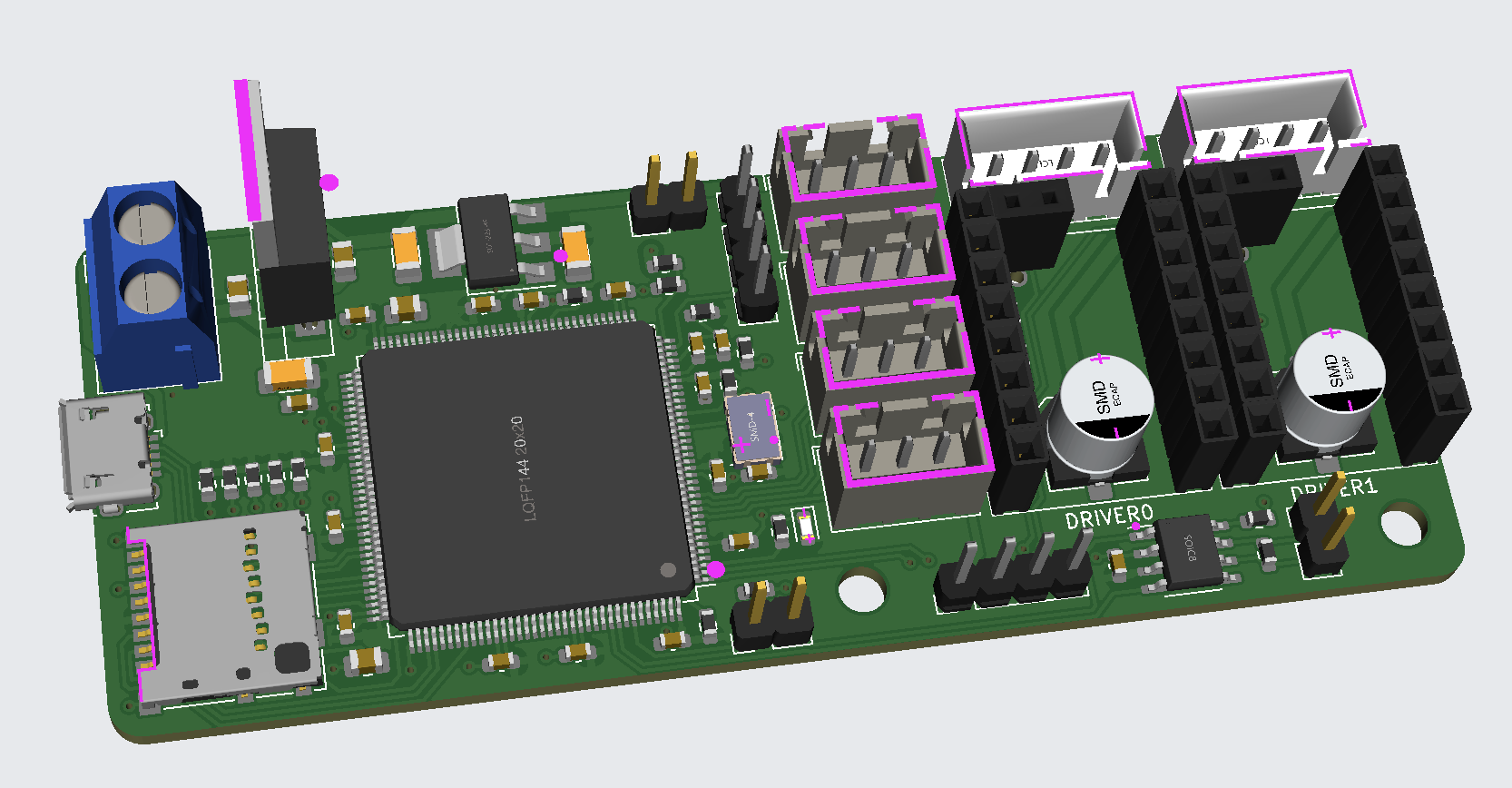
The ERCF Speedboard is my first self-made board for my 3D printer.
I was motivated by the ERCF Easy Board ( https://github.com/Tircown/ERCF-easy-brd ). In the 3D printer itself (a Voron 2.4) I used the mainboard is the Fysetc Spider v1.1, which I recently changed from Klipper to RepRap firmware. There was no particular reason for this, I just wanted to try it out. However, I have lost the ability to communicate with the ERCF Easy Brd as a result. Of course, this is a pity, but also a new challenge.
All this led to the development of the ERCF Speedboard.
Differences to the Easy Board
- A STM32F407 as processor
- MicroSD card slot
- CAN connector
- UART connector
- ESP32 for WiFi
For the size, I tried to keep the same dimensions of the board…. and it worked! Only one of the three M3 holes is missing, but that doesn’t bother me.
Potential for improvement
But there are also a few improvements that could be made. For example, a buck converter for the voltage conversion from 24V to 5V. At the moment I use a L7805 LDO for this. This takes up little space, but gets very hot.
Prototype
Of course I have already tried the whole thing and it works so far. RepRapFirmware runs without any problems on the STM32 fork from Teamgloomy ( https://teamgloomy.github.io/ ). Here I added my board to the code, compiled it and it works.
I had the board itself manufactured by JLCPCB. I think they are great because as a small hobbyist you can have the whole thing soldered at affordable prices. For my two prototypes I paid about 75€ with all the trimmings.

Connection to the 3D printer
Unfortunately the firmware does not support the normal CAN connection of the STM32F407 out of the box. The problem is that the normal CAN only supports up to 8 bytes of data. Therefore, the RepRapFirmware normally uses CAN-FD, which supports up to 64 bytes, plus a few other features. Here my first attempt was to write a custom class for CAN communication that can dynamically distribute the data to multiple packets and reassemble them at the end. After a few tries, it worked and I was able to get my two prototypes of the board talking to each other and controlling each other. However, as expected, the performance was not the best. A second attempt was then to do the whole thing via UART. To my surprise, this worked even better. Of course, it is not suitable for very long cable runs, but what the heck. I then ported the whole thing into my fork for the Fysetc Spider mainboard and tried to get the two boards to talk to each other, unfortunately without success so far. The Spider board crashes with the firmware version as soon as CAN is activated. My assumption at the moment is that the RAM is running full due to the additional tasks that are then running. Only one STM32F446 is installed here, which only has 128KB RAM instead of 192KB.
Translated with www.DeepL.com/Translator (free version)